No Search Result
Connect with us by clicking on one of the following options.
 Sales Enquiry Visit Contact Page
 Grievance Officer grievance_officer@raychemrpg.com
- Other Enquiry info@raychemrpg.com
 Chat with Us Mon. to Sat. 9am to 6pm
-

-
Your List Is Empty
- View Products
Covered Conductors - Indian application & experience
15 September 2022


Covered Conductors - Indian application & experience
ABSTRACT
Covered Conductors which are extensively used in Europe for mitigating the problems caused due to accumulation of snow on the bare metallic electrical conductors in the distribution sector have found use in India too but for different applications in the Distribution and Transmission sectors.
- INTRODUCTION
The majority of Transmission and Distribution in India are still undertaken using the overhead bare conductor system, running on concrete or metal poles or using underground cables. Underground cabling is still sparingly used when compared to the overhead bare lines due to the constraints of cost and difficulty in laying these cables in extremely crowded environment, especially in existing areas.
Few disadvantages of the bare conductor system are highlighted below:
1. Right of way (ROW)
2. Phase to phase distances (Clearances)
3. Construction under and near the liens
4. Electrocutions of birds / animals / humans
5. Clashing of conductors leading to tripping
6. Slashing of conductors due to corrosion
7. Objections to clearing of vegetation
8. Power loss due to large no of joints
2. COVERED CONDUCTORS
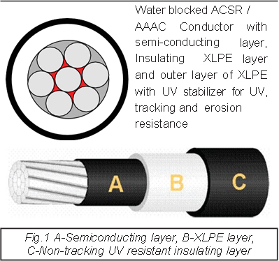
Covered conductors, in the form they are available today, have undergone a number of changes in the construction to overcome the problems found during their usage. The covered conductor started as a compacted conductor with one layer of insulating material extruded onto it in 1984. In 2001, the covered conductor after several changes evolved with longitudinal water blocking, a layer of semi-conducting layer to equalize the electrical stress, with two layers of XLPE, the first being the pure XLPE to provide the necessary insulation and the outer layer being XLPE with carbon black/ UV stabilizer added to take care of the UV stability and to ensure that there is no tracking and erosion of the insulation. This design is suitable for upto 110kV and also suitable for temporary tree contact. The triple extrusion is carried out on the conductor immediately after providing the longitudinal water blocking and stranding, with the conductors still in the hot condition. This effectively provided the additional strength and brings the slippage factor to near unity, thus allowing for the conductor with its insulation to be strung directly without peeling the insulation on the conductor. It also ensures that there is no aluminium oxide layer formed on the conductor.
3. STANDARDS
The applicable standard available as on date for Covered Conductors is EN 50397-1. This specification covers the covered conductors from
1kV to 36kV.
4. TYPE TESTING
Testing of the 66kV Covered conductor was carried out on the basis of this standard itself extrapolating the test methods. All the tests were
successfully carried out and even the leakage current obtained was well within the limits that was specified in the standard for 33kV. Subsequently also several tests like Breakdown voltage test, tan Delta test and PD test before and after environmental degradation tests to prove the life of the insulation materials that are provided on the Covered conductors were carried out by KPTCL on these conductors to access their suitability. Impulse and wet power frequency test were carried with the 66kV Covered conductors mounted on 11-meter spun pole with 66kV insulators to prove the suitability of these conductors in KPTCL system.
5. KPTCL PROJECT
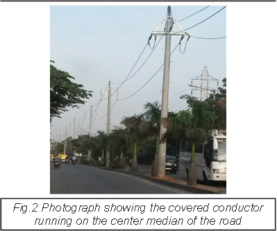
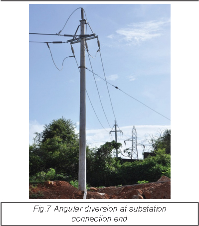
KPTCL had an existing Double Circuit 66kV line between Vidyaranyapura and Yelahanka which had to be converted into a 220/66kV Double circuit line. The work entailed removal of the existing 66kV towers, replacing these towers with taller towers at the same locations to accommodate the 4 circuits ( 2 of 220kV and 2 of 66kV) The catch however was that this line could not be switched off and line clear obtained as the line was supplying power to few important factories and the entire area of Yelahanka and there was no alternate feed for these loads. Multiple times tenders were floated and had to be shelved as there was no way to complete the job without obtaining the shutdown.During one of the discussions with KPTCL, this problem was highlighted and Raychem RPG confirmed that a solution could be provided with Covered Conductors. Based on this assurance and the technical presentation and discussions, a solution was arrived at. This is briefly highlighted below. Majority of the existing line was running in the center of the road or on one side of the road. A proposal was made to bring down the line from the existing tower to a 11-meter spun pole. The spun poles were erected on the foot path of the road with about three-meter clearance between the line and the plants / building. In cases where the existing line was on the side of the road, the poles were erected on the median on center of the road The pole to pole spacing maintained as 50 to 70 meters. The distance between the Covered Conductor to the earthed pole was maintained as 750 mm. The distance between the Covered Conductor to ground was maintained approximately at 6.5 meters. Ampact (Fired wedge) connectors were used to connect the Covered Conductor to the care conductor. Standard suspension and tension hardwares with 66kV polymeric insulators were used to carry the covered conductor for approximately 3kMs and again connected back to the line thus making available the 3kM stretch available for removing the existing towers and erecting the new 220/;66kV Double circuit towers in its place as can be seen from the photographs Once the 3kMs was completed and charged, the covered conductor circuit which was parallel to the main line was disconnected and installed / Shifted for the next 3 kms. This way the entire line was completed and the Circuits along with the 220kV substation that was idling for more than 2 years were commissioned without taking any major shutdown.
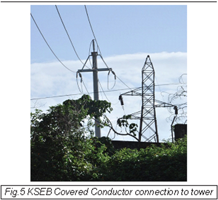
6. THE KSEB EXPERIENCE:
Kerala State Electricity Board had a typical problem. A 66kV Tower in the middle of a new National Highway. Construction of the highway was at standstill as the further work could be taken up only after dismantling of the tower. The tower in question was feeding the 66kV substation at Vizinjam in Kerala where a new port is under construction. A new line was under construction but the same could not be completed and a few towers were not yet ready due to the land disputes at the location. A proposal to dismantle the line was submitted, diverting the existing line along the side road of the highway using covered conductors on 11-meter- high spun poles. The proposal found approval with the electricity department. Here again the tapping was taken from the far side of the 66kV existing tower, to a spun pole, covered conductor was taken along the side road with just about three meters clearance between the line and the tree branches that were on the side of the road. A clearance of 6.5 meters was maintained between the covered conductor and the ground. The existing tower at the center of the road was dismantled and the covered conductor was commissioned thus restoring supply to the substation. The total shut down time taken was just an hour to connect and remove the existing old bare wire connection.
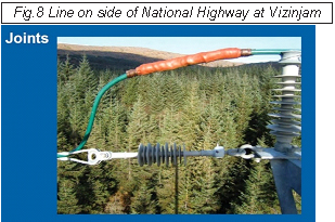
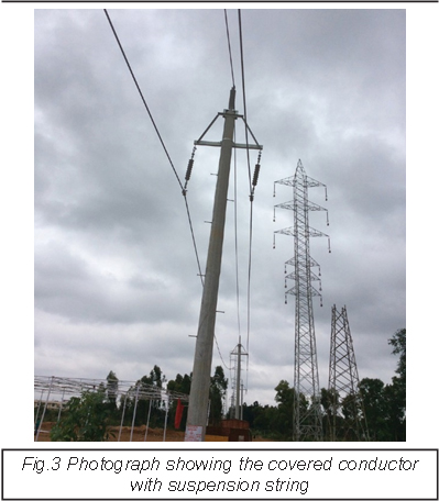
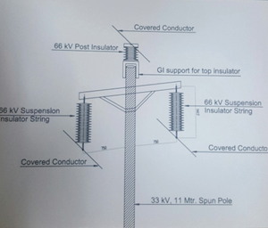
The exact arrangement of the covered conductors for a suspension pole can be seen below
These arrangements could be made, and the problems sorted out because of the availability of the covered conductors.
The advantages were the following
- The electric field around the covered conductor was limited to 1.5 meters
- The breakdown voltage of the material used for the covered conductor was higher than the phase to ground voltage.
- The leakage current on the surface of the covered conductor at 66kV was only 0.8 milliamps making it safe.
- The covered conductor withstood the impulse and wet power frequency withstand test suitable for 66kV.
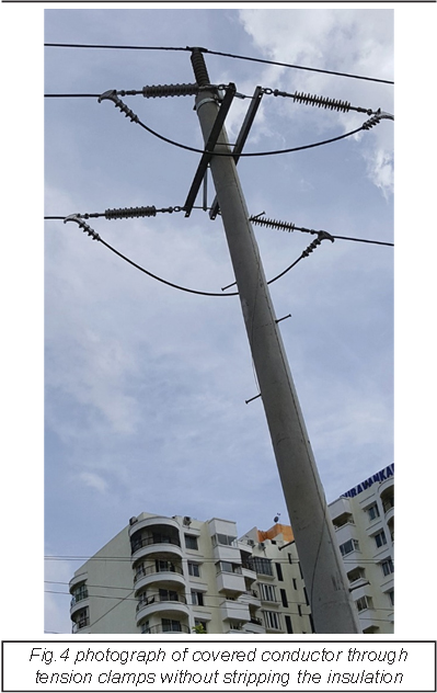
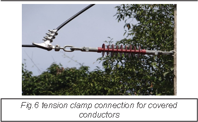
- Slippage factor being unity, the covered conductor is taken directly through the tension hardware ensuring that there is no exposed
conductor at any location. - Even in case of a temporary clashing of different phases of the system, there will not be any tripping of the system.
- The power loss in the system gets reduced very much as there are no additional conductors with joints being used at the tension towers.
Conductors being taken directly through the tension clamp.
This system can also be effectively used as Emergency Restoration system as the time required for putting the system into service is very
low and connections from existing lines can be taken keeping the minimum clearances In the case of 11 & 33kV the phase to phase and
phase to ground clearances can be very much reduced and also because of the very low leakage currents on the surface, become very
safe for crowded localities. In these cases,tapping is taken using Insulation piercing connectors for branches or connections to transformers.