No Search Result
Connect with us by clicking on one of the following options.
 Sales Enquiry Visit Contact Page
 Grievance Officer grievance_officer@raychemrpg.com
- Other Enquiry info@raychemrpg.com
 Chat with Us Mon. to Sat. 9am to 6pm
-

-
Your List Is Empty
- View Products
Challenges in Switchgear Terminations for HV and EHV Cable Systems
07 July 2022

Fency Anthony, Raychem RPG (P) Ltd, Gujarat, India. Ravikant Anekar, Raychem RPG (P) Ltd, Maharashtra, India.

-
Abstract
Based on the fact that the majority of new cable circuits are using power cables with extruded insulation, the technology of the corresponding high voltage cable accessories has also moved from oil/paper to dry materials. Furthermore, the development of the main accessories groups joints and terminations showed major improvement over the last years and represent today intensively developed and complex products. With the advancement in cable and cable accessory technology, we have seen that the footprints of the Switchgear (floor space area) gets reduced thereby resulting into further compactness of the Switchgear. This article shows the current status of the technology of Switchgear terminations. The current challenges are shown and additionally trends and future product developments are discussed.
-
Introduction
Originally (approx. 1920s) stress control technology inside accessories was based on wrapped papers. For this, conductive papers were wrapped in such a way that the end of the semi-conductive layer of the power cable represented a geometrical cone. This shape de- fines the electrical field distribution between earth and high voltage electrode and reduces the electrical stress down to uncritical levels. Today this taping technology is only in use where oil/paper cables are still in operation and not replaced yet. But the oil/paper cables and accessories usage is in decline and will become less important in future. This type of cable and accessories proved less optimal under the newly arising aspects of increased environmental constraints, minimized losses, installation ease, low maintenance, and least cost.
Nowadays the dominating cable insulation material is XLPE up to voltages of 550 kV. An example can be seen in picture 1; this shows the increase of XLPE cables between 1996 and 2006. Consequently, the insulation material of cable accessories changed from impregnated to dry as well [1]. Today there are materials like EPR (Ethylene-Propylene-Rubber) or SIR (Sili- cone rubber) in use [2]. This technology implies some advantages compared to the former used oil/paper technology:
- Quality of stress control element is independent of jointer skills
- Every piece can be 100% electrically tested
- Geometry is predefined
- Easy to install
A considerable evolution has also been seen in the Switchgear termination designs. The governing IEC standards have also evolved and have been adapted by most cable accessories manufacturers. However still some practical adaptability of problems have to be considered by one and all. This article focuses of such challenges for Switchgear terminations and makes some recommendations at the end.
-
Present high voltage Cable Accessories design consideration
Terminations provide the function to enable a connection point to the conductor at the end of the power cable. This connection point is always in the air but could be inside a building or outside. Accordingly, it is a so-called indoor or outdoor termination. If the termination ends inside a transformer or switchgear it is called equipment termination. The main component of every cable accessory is always the stress control element. If the voltage is higher than 72 kV then all available techniques are reduced to the geometrical technology [4]. The higher stresses may not make effective the use of stress control tubes, rather the quantity of these tubes will be high and not practical. This element must control the electric field distribution inside the accessory and ensure that it does not exceed the material limits. At this, the normal operation at rated voltage and also the occurrence of short impulses with much higher levels must be considered.
This paper was presented at the Central Board of Irrigation & Power conference 19-20 January 2016 in New Delhi, India (Challenges in Switch- gear Terminations for HV and EHV Cable System)
-
Switchgear / Transformer terminations
If the cable does not end in air but inside a device then another type of sealing end is used. Compared to the outdoor termination the main components still ex- ist but the hollow core insulator is replaced by a resin insulator with a different geometry. This geometry is made according to IEC 62271-209 which specifies the outer shape of this insulator and guarantees that this part will fit in every standardized switchgear or transformer housing.
Same as for outdoor terminations two types of equipment terminations exist: oil-filled and dry versions.
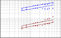
Figure 1: Electric field inside a high voltage power cable
| 100 |
| 10 | 100 | 1000 |
Rated voltage - kV
Figure 1 shows the electric field levels inside a power cable which must be controlled at the end of the cable by the accessory. The red points show the electric field at rated voltage and for the inner and outer sur- face of the insulation respectively. Blue points are indicating the same but for impulse stress. The most critical value for cable accessories is the electric field at the outer surface at impulse voltage. This level de- fines the properties of the stress control element. Cur- rent trends in power cable manufacturing show that the insulation thickness will be reduced further. Espe- cially power cables – so called high stress cables - for rated voltages of 123 kV – 170 kV show a very high operating and impulse electric stress level which can already be compared with the level of 500 kV cables. This increase has to be considered in cable accessory design and requires a verification of established cable accessory designs.
Additionally all cable accessories have in common that they have to fit on the available cable construction. But the design of the power cable is highly de- pended on the intended use and the requirements of the customer and the basic elements such as insulation thickness or cable shielding may vary [5]:
- Conductor
- Semiconductive screen
- Insulation material
- Metallic screen
- Armouring
- Oversheath
The specific setup of a high and extra-high voltage power cable is not standardized and consequently every cable accessory has to be adopted on each cable design. This requires a certain flexibility of the design and system of the cable accessories. Prospectively this will become more important because more and more energy utilities do not insist on same manufacturer of the cable and accessory at the same time.
Both types provide the same main functionality but with the dry version additional features are present:
- Separable connection; Plug-in type termination
- Independent testing of switchgear and cable pos- sible
- No oil filling required inside the termination, hence no waiting or settling time
- Shorter length of cable preparation
- Smaller size and lighter weight of termination
- Epoxy insulator can be fitted by GIS/transformer manufacturer itself
- IEC adapter will match height of existing oil-filled termination
- Dimension complies as per IEC 62271-209.
These are the reasons why the quantity of oil-filled equipment terminations is decreasing whereas the dry version increases. It is expected that the oil-filled version will play only a minor role in future.
Figure 2: Oil-filled equipment termination and dry equipment termination with IEC adapter.
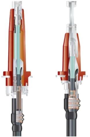
Additionally the stress control element of the dry equipment termination has a special shape. This shape matches the inner geometry of the resin insulator. In installed status the stress control element is pressed against the insulator so that the interface is free of any void or air and no electrical discharges can occur. For this the spring is designed in such a way as to ensure enough compression force of this system for all operation conditions and a lifetime of 30 years. On the other hand this shows that insulator and stress control element will fit to each other only – using of two different suppliers for both parts is not possible.
-
Challenges
The Switchgear termination can be considered comprising of two parts: Male Termination and Female (Epoxy) Insulator. Different challenges are seen for each of these. These could be due to the cable or the testing standards or other reasons. While installation of these terminations are done at site (only), such problems are surfaced then which call for urgent resolution so as to not contribute to project delay. These are discussed separately further.
-
Male Termination
Basic constituents of the male termination are the connector and stress cone. The connector is provided by the manufacturer taking into consideration the cable diameter provided by the cable manufacturer. Note that the connectors provided in HV cable accessories are not range-taking, meaning not much tolerance exists for the connector to accommodate conductor diameter variation at site (Figure 3). So it is preferable that the cable manufacturer provides tolerance values for the conductor diameter. It may be seen that a common solution employed at site would be to remove some conductor strands so as to ‘bring’ such a diameter within acceptable limits of the connector. This will reduce the current carrying capacity of that ‘portion’ of the cable (consider skin effect also).
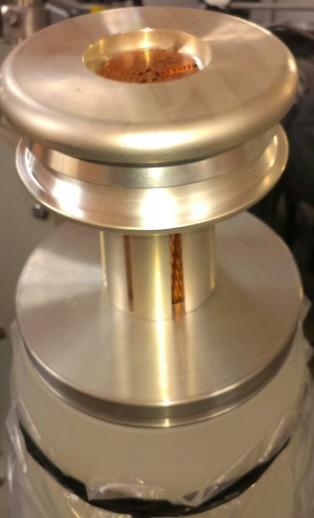
Figure 3: Typical connector insertion problem
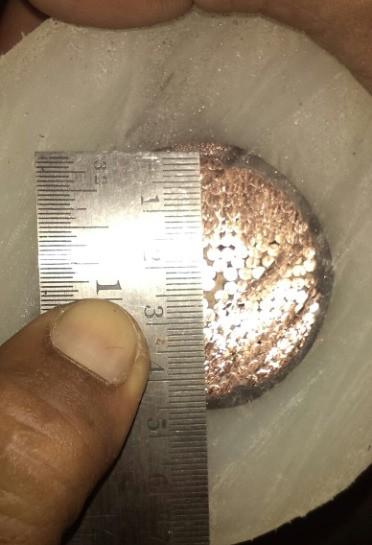
Another problem faced could be the ovality of cable insulation. In rare cases, the cable insulation diameter could be oval rather than being round. There could be varied reasons for this and the most common being that it was created due to sag not being controlled during the manufacturing process itself. What this results is that the stress values at the insulation screen could shoot up than the designed levels. More typically, the stress will be different at different locations around the oval insulation. Since now the stress cone of the termination is placed on the insulation, the stress value to be controlled by the stress cone will be high/varying than its design limits. This is the electrical limitation. Mechanically, the rubber material of the stress cone will be expanded un-uniformly due to such an insulation (Figure 4). When such a stress cone gets into its corresponding Female (epoxy) insulator, air pockets may develop between them and lead to Partial Discharge. If the rubber material is not chosen properly, then cracks could also surface on the stress cone in the long run.
Figure 4: An oval insulation
-
Female (Epoxy) Insulator
The outer dimensions of the epoxy insulator are governed by IEC: 62271-209. This makes it easy for the customer to choose any make of Switchgear termination. But he has to choose both the Male and Female terminations of the same manufacturer. Seldom does the Female insulator of one manufacturer match properly with the Male termination of another manufacturer. However this standardization with respect to the standard allows not only a connection of power cables but also different applications such as blind plugs, test connectors and other apparatus [12].
The insulator must operate in an SF6 environment at a very high pressure (typically upto 4 bar for a 132 kV GIS and upto 8 bar for a 220 kV GIS). The resin and hardener combination used for construction of such an insulator much withstand this continuous operating pressure (compressive from outside to inside). The design of course much be suitable to withstand higher pressures. The epoxy insulator should also be able to seal this high pressure SF6 gas and prevent it from getting dissipated into atmosphere. The sealing surface as mentioned in the IEC: 62271-209 must be with the adequate finish to this aspect.
A key point to note is that in some cases, the Female insulator is directly sent to the GIS manufacturer where it gets tested along with the GIS. Consider the case of a 132 kV GIS termination. As per the cable accessory testing standard IEC: 60840, the AC power frequency test voltage is 190 kV rms and the Partial Discharge test voltage is 114 kV rms. However the GIS standard IEC: 62271-203 has an AC power frequency test voltage of 275 kV rms and a Partial Discharge test voltage of 174 kVrms. This indirectly im- plies that the Female insulator should be designed to withstand test voltages with respect to GIS and not just the termination standard.
The referred standard also defines the scope of supply of components between the Switchgear supplier and the termination supplier including right up to the nuts and bolts. A knowledge of this aspect is essential for the customer to fix responsibility of shortages, in such an unlikely event.
The height ‘l5’ mentioned in the standard is critical as it shows the height of the epoxy insulator available inside the GIS chamber for connection to the electrode. Prior to the current IEC: 62271-209, there was the IEC: 60859. As mentioned earlier in this article, there is an oil-filled design also for Switchgear terminations. This design is more or less obsolete now. A typical design was the longer height ‘l5’ and filling of insulating oil inside such a termination. Consequently, the switchgear chamber for this termination had longer height. If replacement is considered for this design of termination with the new dry type, then an additional extension rod (IEC adapter) should be purchased. The old design needed a difficult oil pumping system and additional parameters factored into the design to prevent oil leakage.
-
Summary
There are many practical aspects and more information available with jointers on the constraints felt in the Switchgear termination installation. An in-depth knowledge of the standards is also important to prevent any wrong selection of the termination with respect to the GIS chamber. This knowledge dissemination process is ongoing and will take place for the next years in order to adapt the current high voltage cable accessories for the requirements of the futures power networks. Needless to say, the cost-benefit analysis also favours the Dry-type equipment terminations. The advantages are also more to reap and are widely becoming popular amongst users.